On country roads in particular, long bends and uneven road surfaces provide precise feedback regarding the chassis.
In addition to the suspension struts and fork legs, the condition of the bearings plays an important role here.
The suspension concept of the SR and XT is over fifty years old. The technology of the swingarm and steering head bearings was invented in Japan back in the sixties. Yamaha, for example, made use of the XS1 and DT1 construction kit.
This makes it all the more important to pay attention to and perhaps even optimize the swingarm bearing today. In our article, we describe the technology and exact procedure for achieving play-free swingarm mounting.
If you find a worn swingarm bearing, it may be necessary to replace some or all of the components. Often the disaster is already apparent when the swingarm pin is difficult or impossible to remove. This is often the case with barn finds or poorly maintained lantern parkers. The last resort is then to pull out or even saw off the bolt. Water ingress causes the bolt and bearing sleeve to corrode and form an intimate bond with each other. Where there should be grease, there is rust. Sometimes, however, you can also find bearing sleeves that are dry but heavily worn due to a lack of grease. The needles of the bearings are then often no longer round and there is a lot of play. Inspectors at the HU and drivers on their after-work tour don't like this at all.
We have complete bearing sets and also the swingarm axle bolt in our range. We also have the dust caps, which also contribute to a functioning bearing.

The principle of swing arm mounting in one sentence:
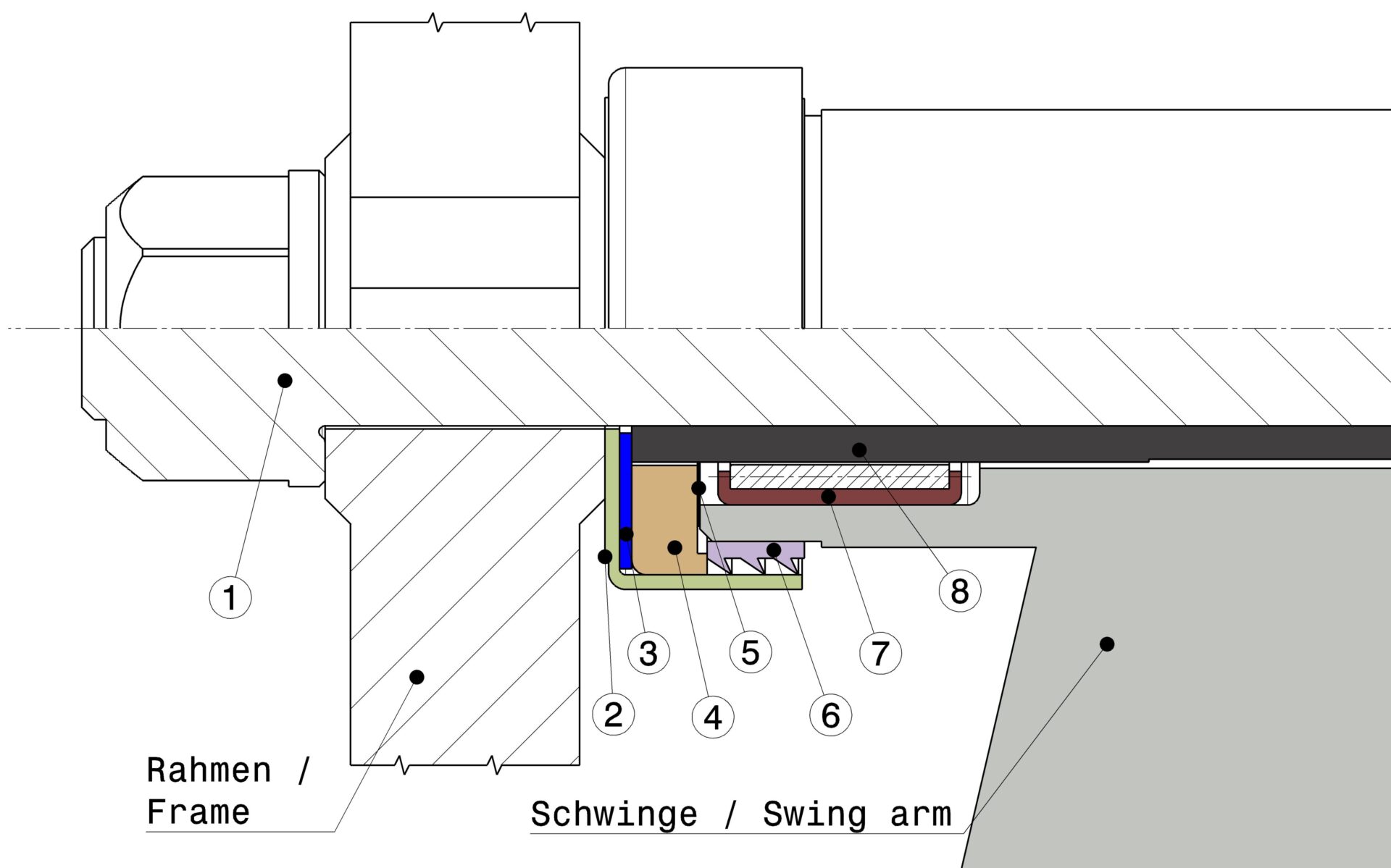
Swingarm axle bolt (1) braces the bearing sleeve (8) in the frame, the swingarm rotates on the bearing sleeve (8) via needle bearings (7) and is supported laterally on the frame via dust caps (2) and thrust bearings (4).
When assembling the swing arm, the existing play at two points in the structure must therefore be determined and compensated for if necessary, as this is the cause of swing arm axle breakage.
If the axle bolt is not properly loaded in tension, shear forces can occur that lead to breakage.
It is worth taking a closer look here.
Here are our tips and tricks from the KEDO workshop.
The frame must not be pulled together excessively when tightening the swing axle bolt.
The frame play should therefore be limited to a maximum of 0.5mm using our shims.

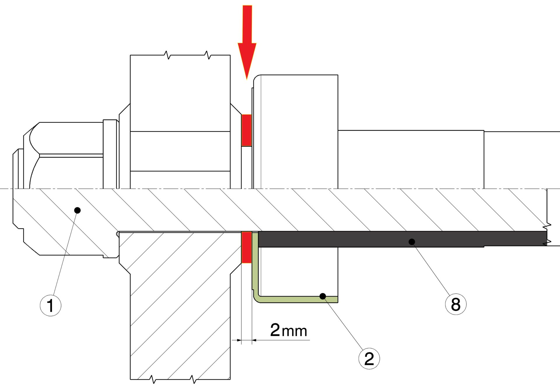
First install the bearing sleeve (8) from no. 21008 into the frame without the swingarm, but with the dust caps (2). With the swingarm axle bolt (1) hand-tightened, there should be a maximum of 0.5 mm play. Any greater play must now be compensated for with spacers (3), which are placed between the dust cap and the frame.
In our example, the total clearance is 2 mm, so 2 spacers of 1 mm are required on each side to maintain symmetry in the frame.

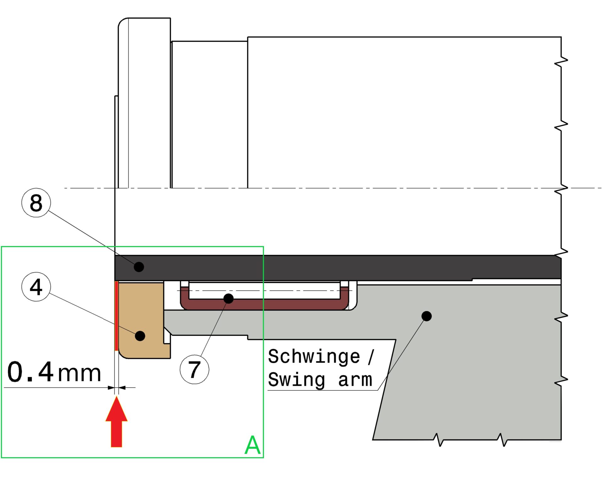
To prevent the swing arm from moving sideways or the thrust bearing (4) from being overloaded, the The distance between the swing arm and thrust bearing (4) must be checked and adjusted if necessary.
When the bearing sleeve (8) including all bearings is installed in the swing arm, it must either be removed from the
thrust bearings (4), or the bearing sleeve (8) must be on the same level as the thrust bearing (4).
After fitting the complete bearing, the swingarm should turn easily
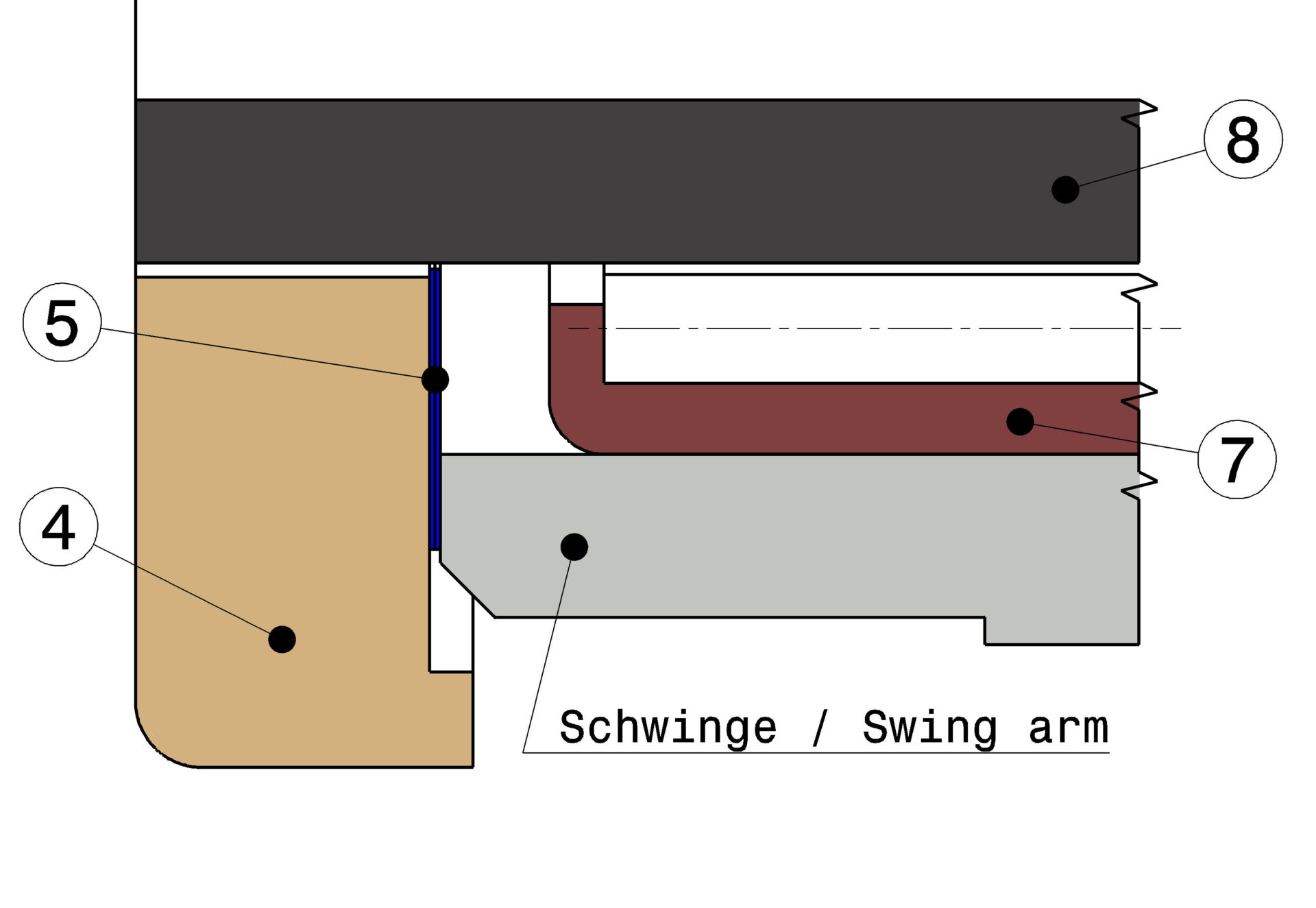
Any side play of the swing arm in the frame can now be compensated for with the shims (5) between
axial bearing (4) and swing arm are balanced without play.
In our example, the total is 0.4 mm, so 2 shims (5) of 0.1 mm per side are required, which are inserted between the thrust bearing and the swing arm.

Do not forget the chain roller or the closed drive chain during assembly.
Please grease the swingarm axle and the bearings well.
However, in order not to distort the torques, the thread of the swingarm axle bolt and the collar surfaces of the axle nut and the frame must be free of grease.
The tightening torque for the swingarm axle bolt is 80 Nm

