Clutch and gearbox

the XT, TT and SR500

Which pulley goes in which position on the main and auxiliary shafts?
We answer these and other questions here.

We recommend that you view this page on your computer monitor. 

Disc special

Two shafts work hand in hand.

Two transmission shafts are installed:

The main shaft, also referred to as the drive shaft in most instructions - on which the clutch is also located.
The auxiliary shaft or output shaft - also called the transmission output shaft in the catalog - carries the rear wheel drive pinion.

In addition to the gear wheels, it is also necessary to check all the installed disks.
As this topic is not fully covered in most repair manuals, we have prepared this little „windshield special“ for you.

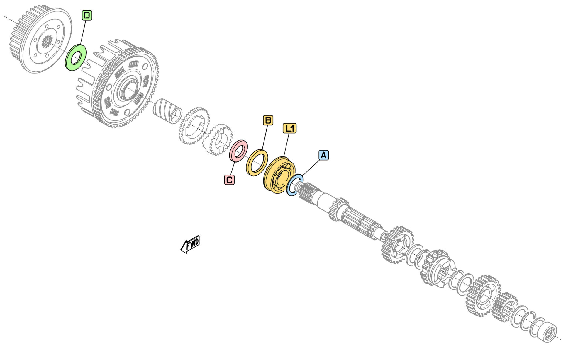
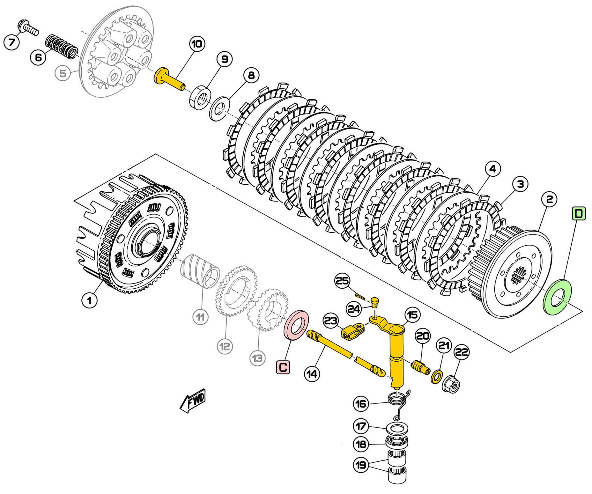
Here are the four discs that we think deserve a little more attention:

  • The shim [A]The shim A, which is located directly on the right-hand bearing of the main shaft. It is often referred to as the „washer of loss“, as it wears out over time during operation and eventually ends up in fragments in the engine - if it is not replaced first. It is only 0.5mm thick and lies against the inner ring of the right-hand bearing. If the disk is already worn down and the remains have not caused any damage in the engine, this is not a problem at first. However, if the engine is being overhauled, we recommend replacing the disk in any case. Without the shim, the clutch actuation is more sluggish. It is necessary to separate the housing halves for the replacement. However, resourceful mechanics can also remove the bearing and replace the disk behind it.
  • The second disk with a special feature is the spacer disk [B], which is only installed in motors with single-row bearings (8 balls) in order to compensate for the different widths of single-row and double-row bearings (36 balls).
    If the engine is younger than 1980 or has been converted to the modern, single-row bearing in the meantime, this pulley is present or is required.
  • The thrust washer 1 [C] behind the clutch is particularly strong with a thickness of 4 mm.
  • The thrust washer 2 [D] has the largest diameter and is located between the clutch basket and clutch hub. When dismantling the clutch, it can easily be overlooked if it sticks to the oil film in the clutch.

Here is an overview of which washer is to be used in which position:

A - Shim

  • The so-called „washer“ on the main transmission shaft
  • ØA = 35mm / ØI = 25mm / t = 0.5mm

B - Spacer washer

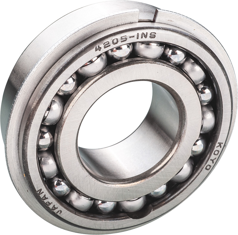
only for single-row clutch bearing

  • is used to convert from a double-row bearing to a single-row bearing [L1] required
  • ØA = 34mm / ØI = 25mm / t = 3mm

C - Pressure disk 1 for clutch

  • OEM ‚pressure plate 1‘, behind the outer clutch basket/primary drive sprocket
  • ØA = 41.5mm / ØI = 25mm / t = 4mm

D - Pressure disk 2 for clutch

  • OEM ‚Pressure plate 2‘, between clutch hub/clutch basket
  • ØA = 50mm / ØI = 25mm / t = 2mm

L1 - Bearing gearbox main shaft right

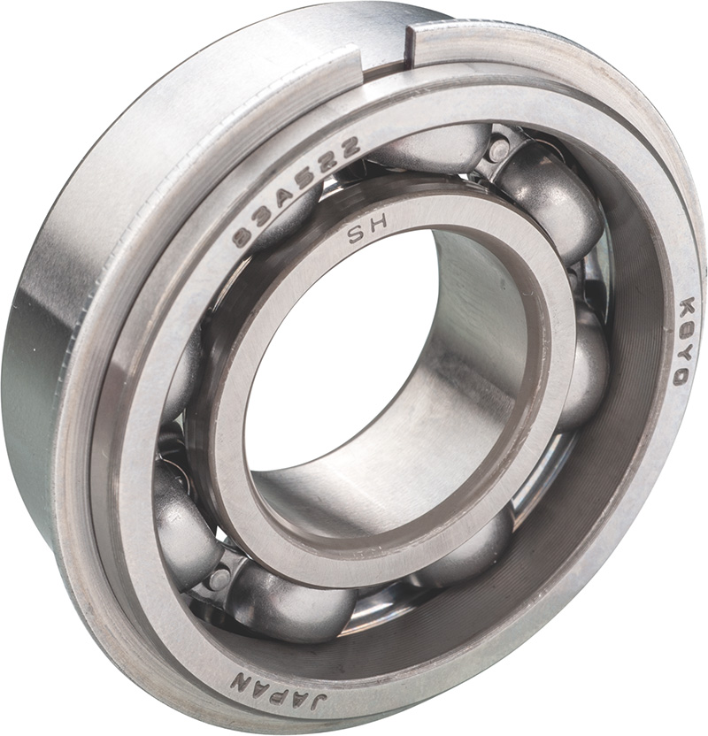
Single-row clutch bearing

  • When using the single-row bearing, the spacer washer [B] required
  • Depending on model year: standard on TT, XT and SR500 from model year 81 onwards

L2 - Bearing gearbox main shaft right

Double-row clutch bearing

  • Use without spacer washer
  • B4205-1N
  • Depending on model year: standard on TT, XT and SR500 up to model year 80

Representation [L2] see:

The clutch

This color coding shows the parts that we consider to be subject to the greatest wear.

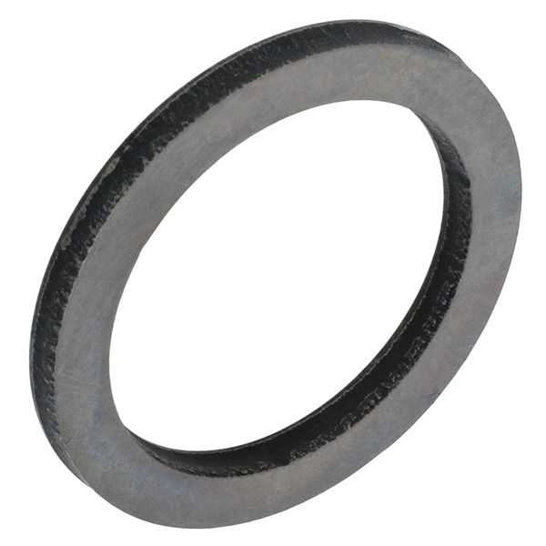
C: Pressure plate for clutch (OEM ‚pressure plate 1‘, 25 x 41.5 x 4 mm)

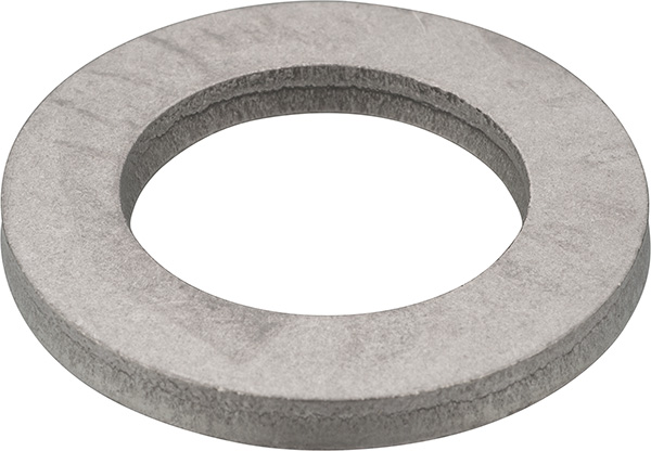
D: Pressure plate for clutch (OEM ‚pressure plate 2‘, 50 x 25 x 2 mm)

The components of the clutch

  1. Clutch basket, article no: 28934
  2. Clutch hub (lining carrier), article no: 10147
  3. Clutch lining set (8 friction plates), article no: 90005
  4. Clutch steel disk set, 7 pieces, article no: 90303
    Clutch steel disk, 1 piece, article no: 90302
  5. Pressure plate - no longer available
  6. Clutch spring, 1 piece - 6x required, article no: 29280
    Soft clutch spring, 1 piece - 6x required, article no: 29280-400
    Clutch spring set reinforced, 6 pieces, article no: 90006
  7. Screw with washer (clutch hub), 1 piece - 6 x required, article no: 27591
  8. Washer clutch central nut (diaphragm spring), 34 x 19 x 2 mm, article no: 27319
  9. Clutch hub nut, M18x1, article no: 28557
  10. Clutch pressure mushroom, article no: 27599
  11. Spacer - no longer available
  12. Drive wheel, pump (42T) - no longer available
  13. Gear Kickstarter - no longer available
  14. Clutch pressure rod, article no: 27605
  15. Release lever (clutch push lever), article no: 10094
  16. Clutch lever return spring (external), article no: 27863
  17. Clutch release lever washer, article no: 28701
  18. WeDi ring release lever (17x28x6mm), article no: 27094
  19. Bearing for release lever, article no: 28407
  20. Locking bolt clutch release lever, article no: 22368
  21. Sealing ring for clutch adjustment screw, article no: 27161
  22. Lock nut with shaft seal, article no: 22371
  23. Hanging bracket for clutch cable, article no: 27778
  24. Bolt with split pin hole, article no: 27777
  25. Safety splint, article no: 27798
    Spring cotter pin, article no: 28141

Problems with the clutch?

In principle, the clutch can cause three types of problems:

  • Sluggishness
  • Loops / poor separation
  • Slipping

Causes and remedy

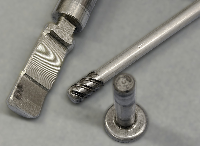
A sluggish clutch is not only tiring for the left hand, it also signals a need for action. The actuation components from the lever to the cable to the release mechanism should be checked. Wear on these elements should be compensated for by adjusting the clutch precisely in accordance with the instructions. However, a worn push rod, pressure mushroom and release lever will eventually make readjustment impossible. The friction discs become thinner and thinner, the steel discs can become deformed by heat and no longer allow complete separation.


  1. If the clutch actuation is stiff, replace the release lever, pressure rod and pressure mushroom. However, an old cable can also be the cause. Ensure correct installation when replacing. The joint of the clutch lever should also be greased. Sluggishness is the sum of many points of contact in the system.
  2. If the clutch no longer separates, check the clutch setting and the condition of the steel disks. The steel disks must be exactly flat. Otherwise, it will no longer be possible to engage neutral and the transmission will be constantly under tension. 
  3. If the clutch slips, which is first noticed in the upper gears, the friction plates are old and hard, smooth and also thinner. Changing them and choosing the right oil is the right thing to do. As a slipping clutch is extremely stressed by the frictional heat, this can also be a reason for the aforementioned distortion of the steel plates.

The gearbox

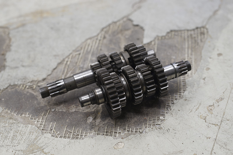
The transmission of the XT500 has five gears and is operated via three shift forks. In principle, the design is very tough, but attention must be paid to the condition of the gear wheel pairs of the top three gears during inspection and maintenance. Typical for high-torque single cylinders.

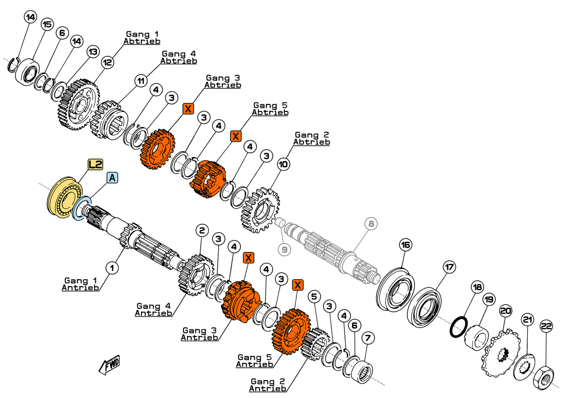
X: 3rd + 5th gear set complete (4-piece gearwheel/gearwheel set, drive/output)

A: Shim 0.5mm (gearbox main shaft), so-called ‚washer‘ 

L2: Bearing gearbox main shaft right (double row, B4205-1N)

Gearbox components

  1. Gearbox input shaft (drive), article no: 27592
  2. Gearwheel 4th gear drive, 24T, article no: 27903
  3. Washer gear shaft, drive + output, article no: 28609
  4. Clip gear shaft, drive + output, article no: 27900
  5. Gear wheel 2nd gear drive, article no: 28992
  6. Washer gear shaft, drive + output (20 x 24.7 x 1 mm), article no: 27794
  7. Bearing 20 x 32 x 13 mm, XU gearbox main shaft left, article no: 27229
  8. Gearbox output shaft (output) - no longer available
  9. Plug for gear shaft lock, article no.: 28956 - no longer available
  10. Gear wheel 2nd gear output , Article no: 28990
  11. Gearwheel 4th gear output, 22T, article no: 27906
  12. Gearwheel 1st gear output, article no: 28989
  13. Washer / thrust washer (20 x 30 x 1.5 mm), article no: 28393
  14. Clip gear shaft, output, article no: 28994
  15. Bearing gearbox auxiliary shaft right, article no: 27230
  16. Bearing transmission output shaft (auxiliary shaft) left, part no: 27228
  17. Gearbox output shaft seal (35 x 62 x 5.5 mm), article no: 10140
  18. O-ring (e.g. gearbox outlet), article no: 10196
  19. Bushing drive shaft, 18.5mm wide, article no: 27520
  20. 16T sprocket, for 520 chains, article no: 91018
  21. Locking plate pinion, article no: 91040
  22. Lock nut pinion (SW 32mm), article no: 91041

Good work

Overall, the transmission set-up is very successful. The gear ratios harmonize well with the power and torque curve of the engine. The engineers have done a good job during development. With a prudent driving style, wear is kept within limits. Incidentally, the shift drum is available in two different versions. Yamaha switched to a needle bearing in the housing at an early stage. Apart from this detail, the parts of the gearbox and the actuation are interchangeable within the models and series.

Choosing the right type of oil is important for a long service life. The oil supplies the engine with lubrication and cooling, but is also responsible for the transmission. The API SG, JASO MA2 specifications ensure shear resistance when used in the transmission and suitability for the clutch running in an oil bath. Our oils from EUROL meet all these requirements.

In terms of wear, it can be said that fourth gear probably works and is stressed the most, while fifth gear also tends to pitting when driving at low revs. The surface of the tooth flanks wears down. It is advisable not to ride exclusively at low engine speeds. The engine is designed with a slightly short stroke. A little speed is always good. The crankshaft and gearbox will thank you.

When gear wheels are changed, the retaining clips should also be replaced. The cost is low but the chance of a long service life is very high.

The assembly

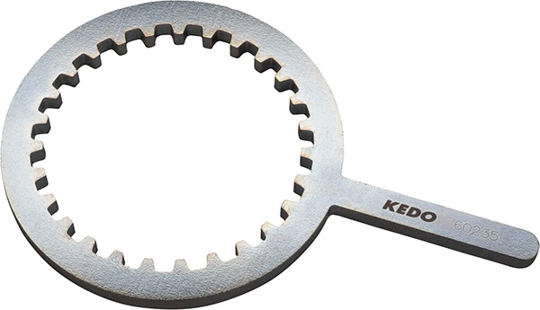
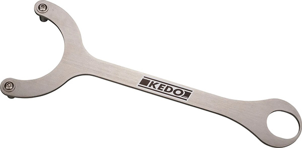
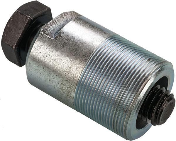
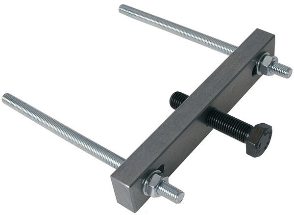
Anyone who has ever dismantled and reassembled an engine knows all about the chicanes and problems that can arise. Here are a few points from us for all those who are tackling this work for the first time. Good preparation pays off here. In addition to the usual tools such as a hexagon socket wrench set and torque wrench, the XT/SR-specific special tools are required. Our clutch basket holder, pole wheel holder and pole wheel puller are just as helpful as the crankcase separating tool.

KEDO clutch basket holder

  • Practical counterholder for loosening the central nut of the clutch basket without damaging it
  • Particularly safe one-handed operation, can be easily attached to the vehicle
  • Sturdy workshop quality, galvanized to protect against rust

HD pole wheel counterholder

  • Supports itself on the swingarm axle bolt, preventing the vehicle from being levered out
  • Requires a 22 mm socket with a maximum outer diameter of 32 mm (item 20115)
  • Suitable for all SR400, SR500, TT500 andXT500

Pole wheel puller M27x1.0 left-hand thread

  • Particularly robust workshop version
  • The use of the bronze sleeve is recommended to protect the sensitive crankshaft end Art. 60626

KEDO crankcase separating tool

  • Indispensable when separating the crankcase halves
  • Especially for YAMAHA SR500/XT500 and TT/XT600 models
  • Robust workshop quality, galvanized to protect against rust

The motor should be thoroughly cleaned and the workplace should be large enough, clean and properly lit. As the bearings and shafts are inserted into the housing halves, shimming material is required to ensure that everything is flat and stable. Sorting boxes are useful for the small and individual parts. All new seals and shaft seals, surface seals from the tube as well as locking plates and bushes should be ready.

Here are our points, without any claim to completeness:

  1. The first and most important tool for starting on the engine housing is the 5 mm Allen key. It works best when the screw heads are clean. 
  2. The sealing residue from the side covers must be removed. Do not forget the blade and reinger.
  3. When separating the halves, there is usually also a lot of dirt and oil to tackle inside the housing. Paper towel, brake cleaner and compressed air help here.
  4. Clip pliers, soft-face hammer and screwdriver help with the clips and locking plates.
  5. The gentlest way to install bearings and shafts is to work with heat and cold. Hot air blowers, hotplates, ovens, cold spray and freezers are a huge help here.
  6. When fitting the bearings, it can help to use aluminum tubes to the same dimensions as the bearing inner rings and outer rings. These are things that usually see the light of day in the workshop during the second engine overhaul. Everyone has their own experience here.
  7. When inserting the shafts, always check that they run smoothly and use plenty of oil. Working cleanly also means ensuring that no dust or shavings get into the bearings. Anyone who has ever done this in the dunes of Africa will laugh now.
  8. We recommend studying a repair manual beforehand and keeping it to hand in the workshop. The classic from the Bucheli publishing house: The edition for the 1975-1979 model years, followed by the later editions for the second generation XT500 from 1980 and the editions for specific SR500 models.

Repair instructions XT/TT/SR500 1975-79

Repair instructions XT500'79-

Repair instructions SR500 -'83

Repair instructions SR500/T'84-

People help each other. It works: the worldwide screwdriver community.

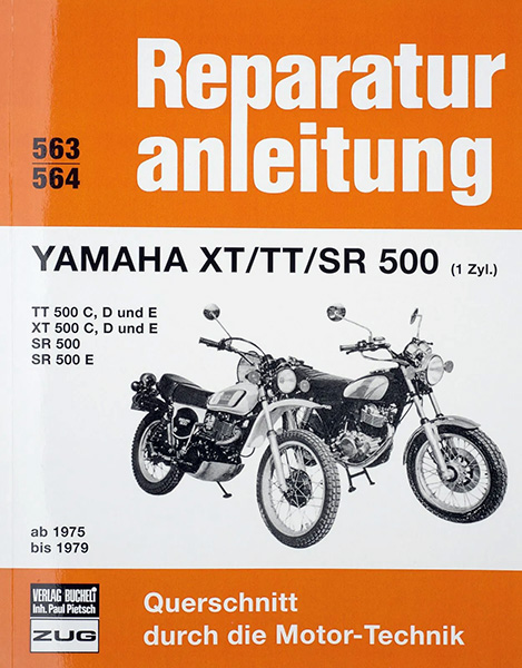
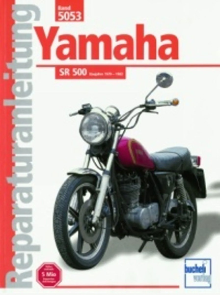
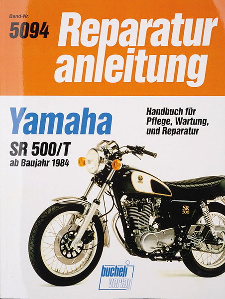
At this point, we would also like to mention the achievements of the community. Hardly any other 4-stroke engine has ever been documented so comprehensively and in such detail in the fan community. In addition to the many XT and SR500 Internet forums in the German-speaking world, the „Bucheli project“ outstanding. This project closes gaps that can be found in the popular repair manuals published by Bucheli Verlag. Swarm knowledge is bundled here. Collectors, mechanics and enthusiasts add their - sometimes highly professional - mustard. The result is a comprehensive reference work on the technology of the SR500 and the XT. A classic among the Web 1.0 sites and highly informative.

We were at the Scrambler Fever in Poland last weekend and it was really good again! 2 days of rattling through the woods with about 70 other enduro enthusiasts. Due to the extreme drought, many forest roads were a sandy hell. Everyone cursed about it, many crashed but everyone had a big grin on their face afterwards. More about this event soon....

Current offers, news & much more
in our new newsletter

Your registration could not be saved. Please try again.
Your registration was successful.

KEDO Newsletter

Sign up for our newsletter to stay up to date. We send out a maximum of one newsletter per month.

We use Brevo as our marketing platform. By clicking below to submit this form, you acknowledge that the information you provided will be transferred to Brevo for processing in accordance with their terms of use

Kedo Live

There is a lot of news on Instagram.